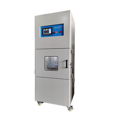
Equipment Overview
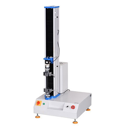
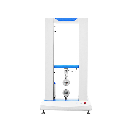
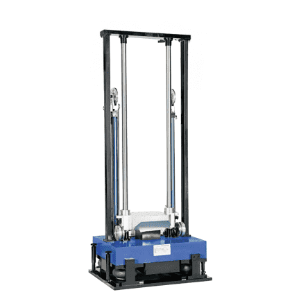
Mechanical Shock Test System is a fully automatic pneumatic lifting vertical shock test system. It is used to measure and determine the impact resistance of products or packaging, and assess the functional reliability and structural integrity of the test product in a shock environment. Mechanical Shock Test System can perform various conventional classic shock tests to realize the shock wave and shock energy that the product is subjected to in the actual environment, thereby improving the system or optimizing the structure of the product. It is vertical shock test equipment with novel design, high degree of automation, simple operation and convenient maintenance.

Standards
MIL-STD-810 Method 516.5 Military / Classical Shock
MIL-STD-883 Microelectronics Shock
TIA/EIA-455-14 Fiber Optics Shock
TIA/EIA-455-14 Fiber Optics Shock
IEC-60068-2-29 Bump Shock
EIA-364-27 Electrical Connector Shock
RTCA-DO-160 Airborne Equipment Shock
GR-1209-CORE Component and Module Impact
MIL-STD-810 Method 516.5 Military / Classical Shock
MIL-STD-883 Microelectronics Shock
TIA/EIA-455-14 Fiber Optics Shock
TIA/EIA-455-14 Fiber Optics Shock
IEC-60068-2-29 Bump Shock
EIA-364-27 Electrical Connector Shock
RTCA-DO-160 Airborne Equipment Shock
GR-1209-CORE Component and Module Impact
Technical Specifications
Rated load (kg) | 100(including fixtures, test pieces, sensors, etc.) | ||
Working way | Free fall, vertical shock | ||
Shock pulse waveform | Half sine wave | ||
Shock peak acceleration (g) | 10~100 | ||
Shock pulse duration (ms) | 4~40 | ||
Table size (L×W) | 1000*1000mm(or custom size) | ||
Equipment installation requirements | Free foundation, air spring cushioning and damping | ||
Power Requirements for Table | AC220V±10%,50Hz,2kVA | ||
Working Environment | Temperature(℃) | 0~40 | |
Humidity(25℃) | ≤90% (non-condensation) | ||
Stable air source(MPa) | ≤0.8 | ||
System reliability | Average cumulative working time without failure ≥1000h; The storage time of rubber products in a clean, normal temperature environment is not less than 3 years | ||
Standards | MIL-STD-810F IEC68-2-27 | ||
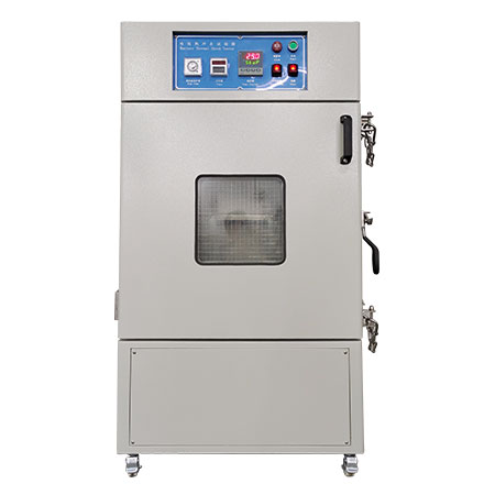
Equipment Overview
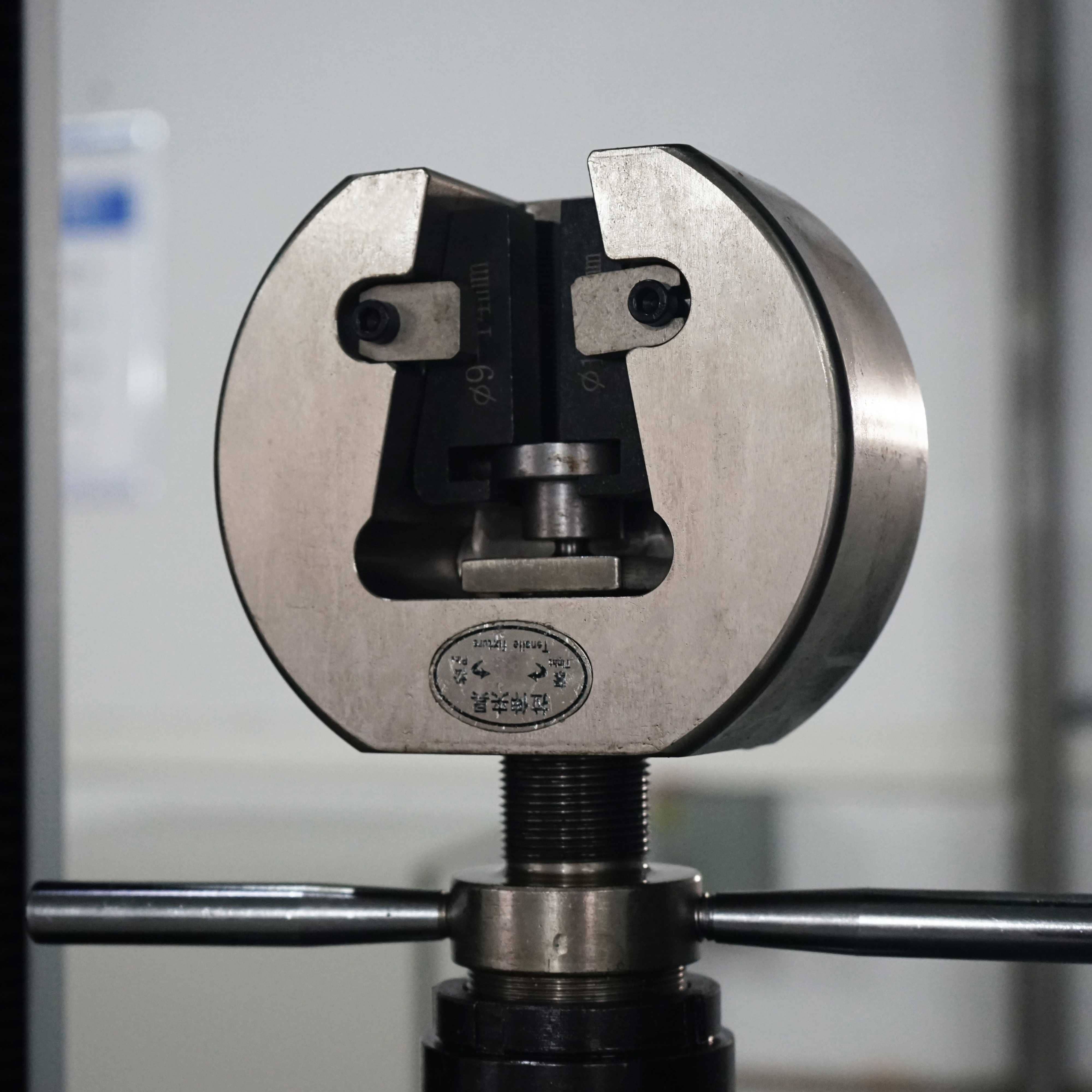
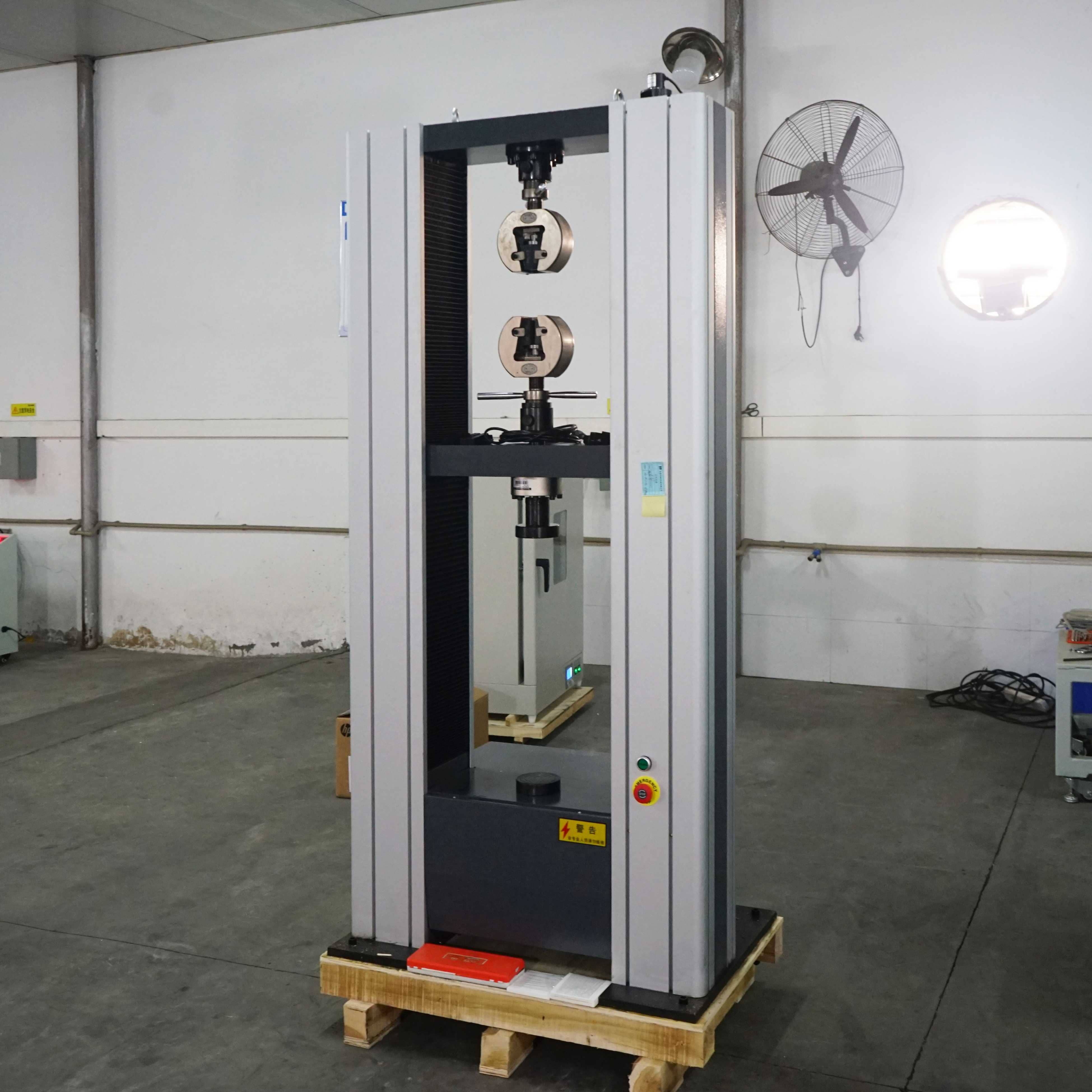
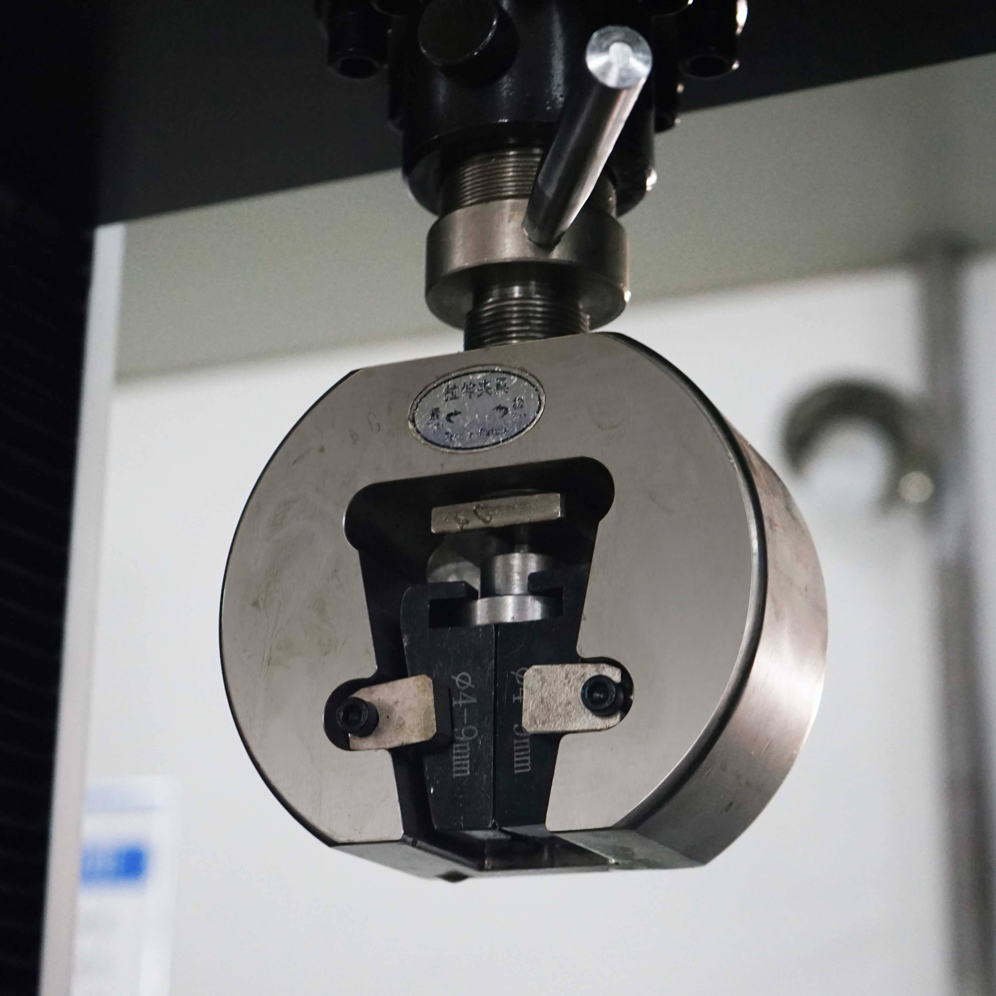
Mechanical Shock Test System is a pneumatic lifting vertical pressure shock tester. The product structure is shown in Figure
Mechanical Shock Test System has an ingenious design, simple and reliable structure. The test sample is installed on the worktable, which is guided by two high-precision sliding guides and can move up and down. The two cylinders are connected to the worktable by sliding guides. When the cylinders are inflated, the piston rod rises to drive the worktable to lift. The workbench is lifted. When it is raised to the set height, the cylinder quickly deflates, and the bottom surface of the worktable hits the waveform generator to complete a shock process. It can be seen from the above shock process that by adjusting the rising height of the worktable, different initial shock speeds can be obtained, and thus different shock overload values can be obtained; while changing the stiffness of the waveform generator, different pulse width value can be obtained. With the coordination and cooperation, various shock test waveforms that meet the design index requirements can be obtained. By adjusting the input air pressure, the shock frequency can be controlled to meet the test requirements. Mechanical Shock Test System is equipped with a half sine wave generator. The half-sine wave generator is mainly made of engineering rubber (considering the stiffness and cohesive force of rubber) and felt pads of various thicknesses. Different thicknesses are connected in series to form multiple stiffnesses to achieve different shock pulse widths, as shown in Figure 3.
Standards
MIL-STD-810 Method 516.5 Military / Classical Shock
MIL-STD-883 Microelectronics Shock
TIA/EIA-455-14 Fiber Optics Shock
TIA/EIA-455-14 Fiber Optics Shock
IEC-60068-2-29 Bump Shock
EIA-364-27 Electrical Connector Shock
RTCA-DO-160 Airborne Equipment Shock
GR-1209-CORE Component and Module Impact